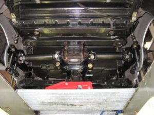
One part of the whole suspension overhaul is the rebuild of the trailing arm.
The current trailing arms are starting to ge a bit rusty and the rubbers of the trailing arm and the strutrods aren’t what the should be after 33 years of duty.
Before removing the trailing arm you have to do the follwing:
- Loosen or remove the leave spring (See section leave spring)
- Remove the strutrod (This eases the removal of the driveshaft. Note/measure the position of the camberbolts)
- Remove the drive axles (At least at the arm side)
- Remove the rear brakes or tie it to a point of the car with some wire
- Remove the parking brake wire
- Remove the shock absorber from the arm
- Remove the sway bar (If present)
- Remove the trailing arms by taking out the shimms (record the thicknesses on each side of the t-arm)
- Then loosen the bolt which is going through the trailing arm
In my case, all is taken apart and overhouled. The car had to be alligned anyway so I didn’t bother to note the positions of the camber bolts.
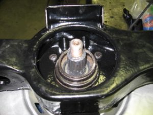
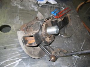
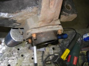
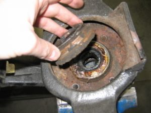
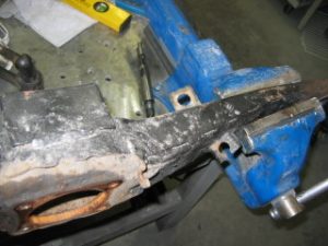
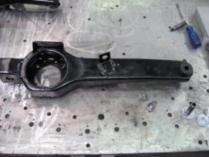
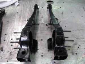
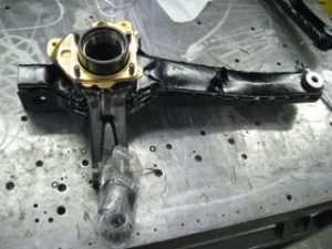
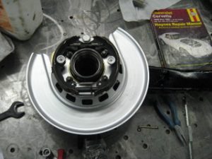
When the arm is taken off, it should like this:
A bit rusty, so some hammerite will do the job until a full body off.

Now we are at my work where it is warm in the winter and plenty of tools/machinery availlable. The strutrods are still atached to the arms so they are taken off. Well that was the plan.
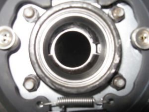
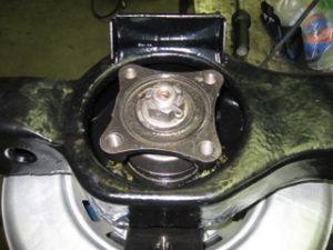
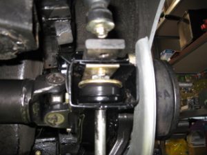
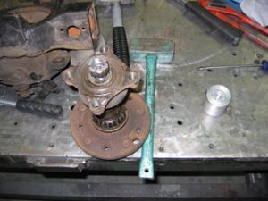
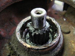
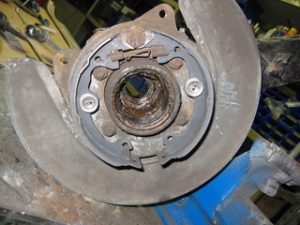
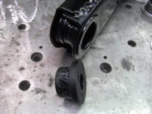
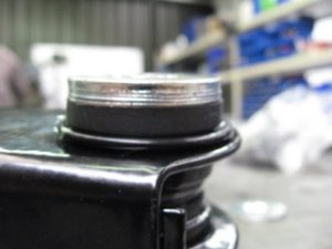
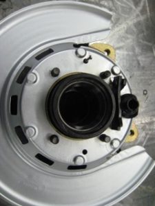
Here is the rear spindle flange where drive axle is connected. Remove the cotterpin, the bolt and take of the spindle flange. The spindle has splines so slide it off in axial direction.
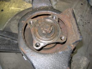
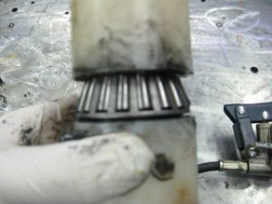
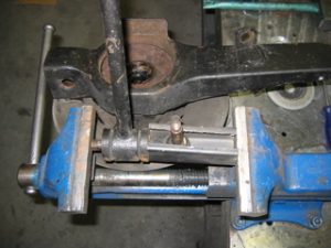
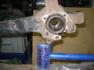
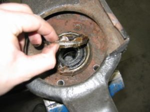
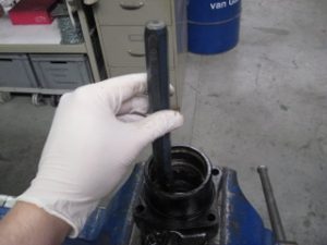
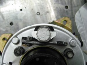
I would advice a purchased spindle knocker. But I was too impatient to order it in the USA and wait for it. My strategy was a piece of soft aluminium which was lathed to fit onto the thread.
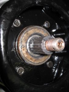
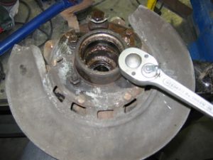
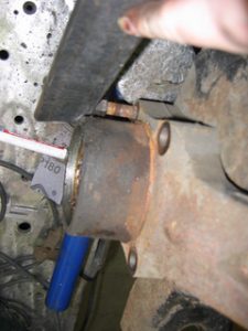
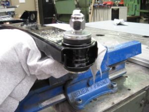
Here the tool is slid over the spindle thread. The ony thing now remaining is the smaller version of “the Hammer of Thor” as we call the green thing. Hit the aluminium block as ‘direct’ as possible. So no off-angle impact.
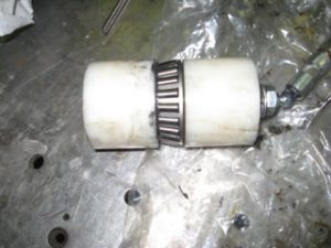
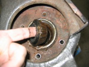
After quite some hammering and patience, the inner bearing came loose.
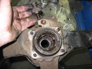
Keep the whole assembly together and don’t mix it with the other spindle. Record the thickness of the shimms used.
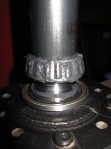
The Aluminium tool has suffered a lot. Better this one than my spindle threads!!!
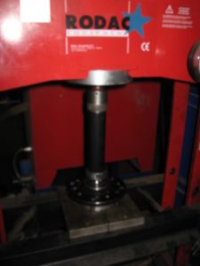
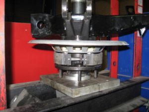
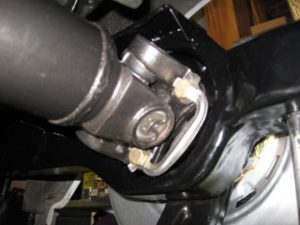
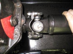
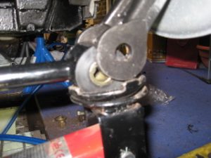
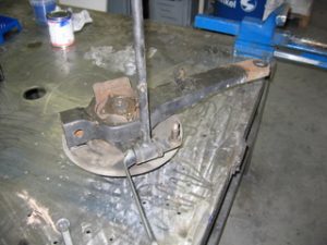
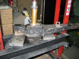
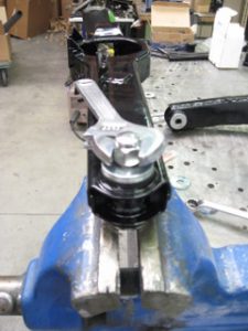
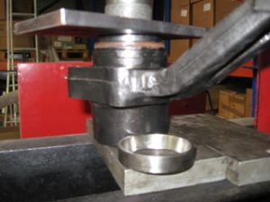
Here is an attempt to loosen the pin which holds the trutrod. A bit rusted together so this method didn’t work. The hydraulic press didn’t have any problem with it. They both came loose with a big bang.
Lets go furter in demolishing…… The parking brakes are next to be taken off.
Then these bolts to take away the dust shield.
The anchor for the parkingbrake. This is attached to the caliper mounting plate.
Now pry off the caliper holding plate (it has probably a real name….)
Now the whole assemly is resting on the real hammer of Thor. The holding plate is still on.
To remove the caliper plate, just put the nut on for a bit and tap on the nut to genly hammer the bolt out. The neck of the bolt is splined and pressed into the trailing arm.
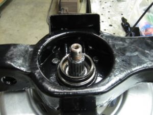
Here is the backside of the story. Now we continue to disasemble the inner bearing.
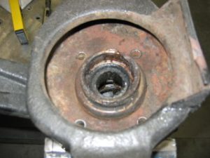
Gently tap of the dust cover.
Now remove the oil seal.
And take out the bearing. After all they didn’t look bad.
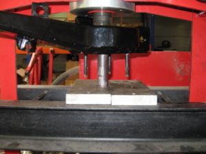
Now the bearings are out the bearinghouse itself can be pressed out. Again gently with the press. Make sure the trailing arm itself is well supported.
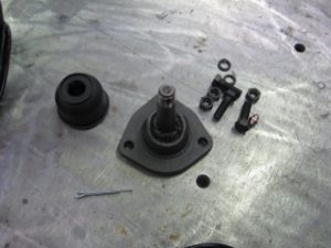
And finally a trailing arm without any parts.
Reassemble the trailing arms
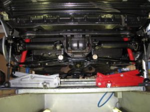
Ok, now it’s time to reassemble the trailing arm. In the picture below is a black hole, or better a rusty hole where once the training arm used to be.
The arm is taken off and sent away with a lot of other parts for sand blasting and for galvanizing. Not the dip galvanizing type, but molten zinc is sprayed onto the metal. The final treatment is black powdercoating, which creates a mooth surface, resistant to impact and easy to clean.
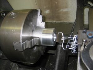
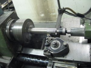
First I decided not to buy a spindle setup tool but to enjoy making one myself, since I had the education for this a long time ago.
The first step is to take a large piece of metal, where the geometry of the spindle can be machined.
The trick is to have the same dimensions, exept for the locations where normally a press fit for the bearings are situated. This tolerance is now a loose one. Loose enough to slide the beraings over, but no too loose.
The several diameters are taking shape.
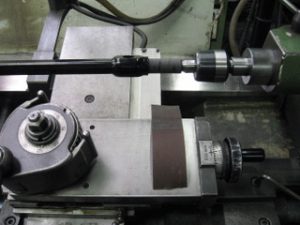
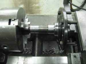
This is the side of the lathe. Now the gears are set up to cut the tread onto the spindle. For me this was a long long loooooong time ago since I’ve practiced this at school. This must have been in 1995 or something.
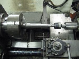
A detail of the cutting process. It takes a long time becouse I don’t want to ruin my work.
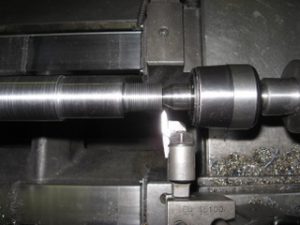
This is looking like a thread now. Each time I tried to fit the nut to check if it runs properly.
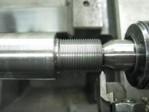
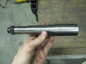
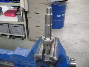
Here is the result.
Now the lathe is used for taking off the thick layer of powdercoating, otherwise the metal bushing won’t slide over. The allingnment was difficlut and lathing was not possible (no cucks with independant teeth), so i’ve taken off the exces material with sanding paper.
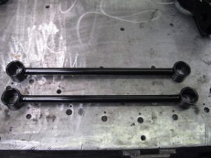
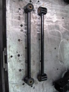
Looking at these strutrods makes me happy again. Really a good painting job.
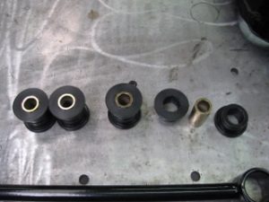
These PU bushings were ordered in a large kit. And yes, PU beacause I don’t want to do this again on my corvette.
Assembling the PU’s into the strutrods was fun to do. Don’t forget to grease the PU with the special included grease to prevent squeeking of the PU in normal operation.
In this case I resorted to the press because it was there. A vise was just as good.
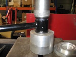
And here is the result, waiting for the joy to be installed.
The PU bushing kit was not inlcuded in the big set, so it was ordered separately including a simple but effective installation tool.
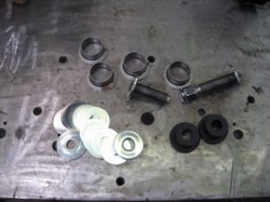
These PU bushings need to be lobricated as well, this helps in installing. To be honest I forgot to take out the outer sleeves of the PU bushings out of the trailing arm. This was actually a benefit afterwards. Now they are galvanized again and powdercoated.
So, put them into the traing arm.
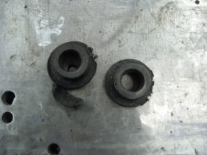
Oh, by the way… Here are the old rubber bushings.
The other side the same and put in the inside sleeve with the attached washer. The piece wich is podtruding throug the PU bushing has been mashined down. It’s thinner than the section inside the bushing.
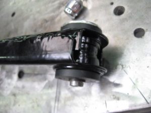
The kit includes shimms to fill up the room between the PU and the washer. I chose to put all washers on one side only. The trailing arm needs to be shimmed anyway for allignment.
The machined section of the inner sleeve is now bent to the outside and over the washer by a bolt and a conical nut. This helps pressing the PU rubber and ‘rivveting’ the inner sleeve onto the washer.
Clamping the bolt into a vise will free your hands to turn the nut.
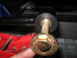
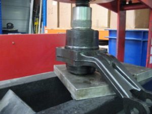
The next thing is the bolts to clamp the bearing assembly. One bolt is put into a metal pipe. Then the press is used to press onto the neck of the bolt to seat it into the trailing arm.
And voilla, each job is done in stereo.
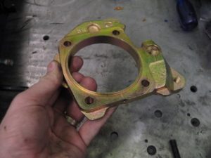
This is one thing I was verry happy with. Just acros sthe border is a Belgian company which is specialized in galvanizing all kinds of stuff. A bucket full was delivered and the brake caliper bracket was one of the components. They really are as new new.
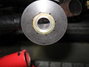
Now the bearing houses are next. First tap out the outer bearings and clean the inside. In this case I have used a chinsel.
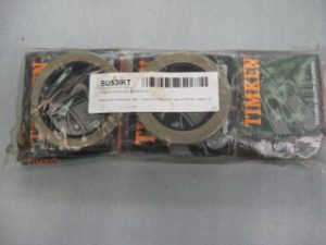
I’ve used the bearings ordered from Ecklers. Real USA bearings and I knew the brand Timken. This is a complete set for one wheel.
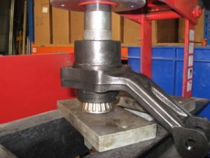
Again the press is used to press in the new outer bearings. Use a tool which is just smaller than the outside of the bearing. Seat the bearing track until it will not move again.
The same is on the other side.
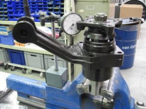
And now it is time to use the bearing assebly tool. For easy clamping in the vise, two flat faces were machine on the bottom.
Put the biggest bearing at the bottom and slide over the bearing house. Then place the disctance holder and the shimm inside.
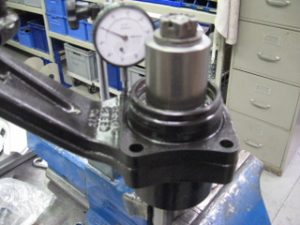
Now put on the spindle flange and torque it down with xxx lbs/inch.
Now with a dial clock, check for axial play of the spindle.
The play should be between xxx and yyy.
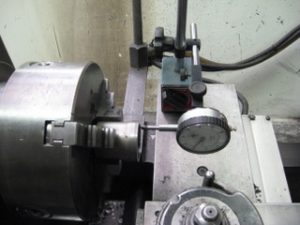
The spndle flange was bithering the measurement process. The dial gage could not measure on a flat surface, and the closer to the spindle, the more accurate the axial play measurement.
So another adapter was machines to have more clearance for the dial gauge.
The play I had was too less. To correct this, different shimms should be used. But…… These weren’t in the bearing kit and I didn’t order a shimm kit. When shimm kist are used, you have to compromise on the tolerances.
Now I resorted to the lathe again. A grinding machine ( don’t know exactly the name in englist) is better, this takes off in parrallel 0,001 mm if needed. When using a lathe, this will resort into a loooooooooong time to allign the surface to be machined. And this was done a couple of times. This will keep you busy on a Saturday.
All play in all bearings have been set and to prevent switching of measured assemblies, hey are tied up to the corresponding trailing arm. The nuts have been installed to pull the brake caliper bracket onto the bearinghouse.
Install the dustshield, the parkingbrake lever and the pin which will hold down one brake shoe. Don’t forget this one!.
A detail of the dust shield. This one was galvanized as well, but not perfectly. That’s why the silver paint.
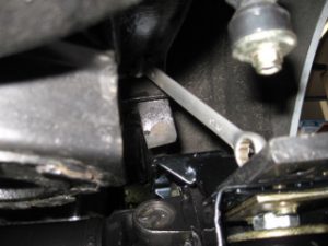
A detail of the parking brake. It took some time to figure it out how it should fit, even when it was indicated with L and R…………
The brake anchor bolt is greased with copperbased grease. Jus in case I need to loossen it when im retired in 35 years.

And here the bolt is installed.
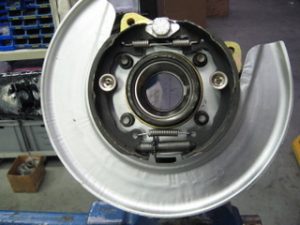
With the brake shoes installed it should look something like this.
To prevent difficulties in pressing over the inner beraing rings, the hub was placed into the lathe and the bearing position was polished. Maybe it doesn’t help, but it sure doesn’t hurt.
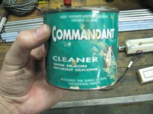
This is the stuff I used to polish the metal. The stuff is actually a cleaner for worn paint, so quite a fine grain.
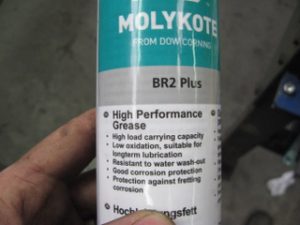
Now it is time to put on the bearings and this means the bearings fist need to be greased. I’ve selected molycote high performance grease. Maybe the car wil go a little bit faster with this grease……..duh!
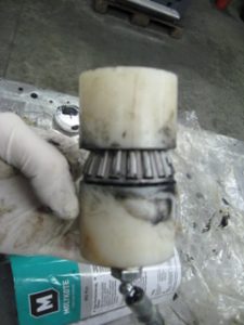
Here is a picture of the bearing grease tool I’ve fabricated. The bolt which holds the 2 plastic parts together is hollow. The end is blocked by the grease nipple and at the centre of the bolt a radial hole is drilled to let the grease escape in side the bearing which is clamped between the 2 plastic blocks.
It is my advice to wear rubber gloves, because it will be messy.
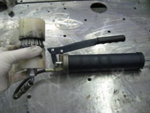
A close up of the hight tech bearing greaser….