
The main topic of this year (now august 2009) is to search for more torque and horses!
The current engine is out of a C-20, C-30, 2500 or 3500 heavy truck. The block has originally 160 HP. and 250 lb/ft As I found out on the heartbeatforum in the netherlands.
The big advantage is that it is a 4-bolt mains block which is a bit stronger than an engine where the crankshaft bearing caps are held with 2 bolts
The cylinder heads match the truck type. Our head number is 3998991 found on www.mortec.com
The nuber information says: year 72-73, engine size 307/350 CUI and 75 cc chambers and a 1-8,5 compression ratio.
To improve performance I need better flow in the heads, bigger valves ( with 3 angle valve job) and a matching camshaft.
After lot’s of reading and searching on the internet I came to the conclusion that randomly picked components won’t work. That’s why I’ve chosen the easy route which leads to a hopefully satisfying result. I’ve purchased Edelprock performer 64cc heads with a matching Edelbrock 2102 camshaft.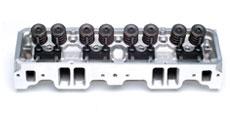
I’m hoping to reach 340Hp and at least 400 lb/ft of torque. The intake is an performer 2101 and flowtech headers are installed. Everything is ok now only the flow and compression ratio is the bottleneck for corvette worthy torque and horses. The static compression ratio will go up with 1,5 from 1:8,5 to 1:10. The dynamic ratio will be a guess. This is because of the overlap of the intake and exhaust valve and rpm. The compression can be tested with a tester which I have bought in an american dumpshop (www.valkenpower.nl). Sometimes buying tools can make a man as happy as a woman buying clothes.
A lot of horses can be extracted from the chevy smallblock engine, even well above 500. But what happens then, how reliable is the block, what is the next weakest link? Gearbox? Lid of the differential? That’s why I’m aiming for 300+ HP and approx 400 lbs/ft of torque, Which is approx 540N/m.
I’m very curious to see the condition of the cylinder walls when the heads are lifted. Hopefully I like what I see and continue with the head swap.
So again an open heart operation for a firsttimer surgean. Luckily I’ve seen a couple of video’s and attended one engineblock meeting where we have assembled an engine with a couple of ethousiasts.
With some courage and common sense I’ve started to work on the corvette.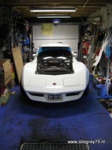
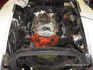
Don’t look at the junk! To have enough working space and prevent damage I’ve stored the hood on top of the car!
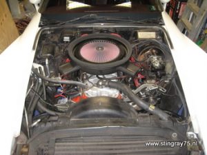
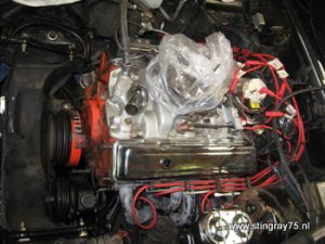
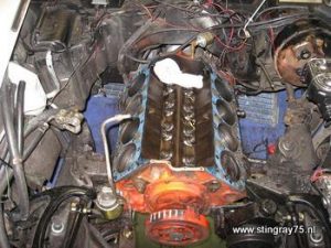
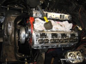
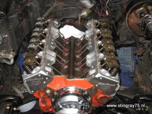
This is how it looks now. Cast iron heads, Edelbrock performer and K&N filters.
It will be soon a lot emptier. Enough too to place an extra v8 engine 😉
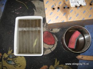
Step one could be taking way the air filter
Drain the radiator. Below there is a small plug.
My mistake was the assumption that the block would drain as well. Whis is partially true, the best way is to unscrew 2 bolts in the engine block to drain the engine. Next time I’m in the pit I’ll make some pictures.
Space reserved for the drain bolt picture
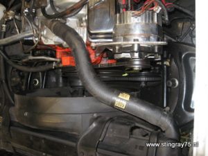
Remove the alternator. The tensioner bracket is mounted to the cylinderhead. I must not forget to spray paint these components.
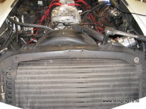
The next one is removing the airco radiator and the engine radiator.
The airco pump was removed previously. Make sure you have somebody to vacumize all the gas out of the system and to refill the system after youre done.
Both radiators are mounted ont he top and in rubber push-in rubbers below.
First the fan is removed including the waterpump. Be shure to make puctures of the way the belts run over the different pulleys!
When the fan + waterpump are removed, the fanshroud and radiator hose connections must be removed before removing the radiators.
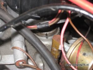
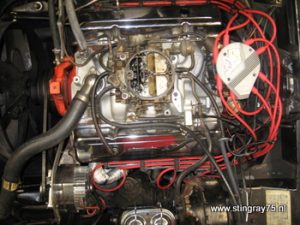
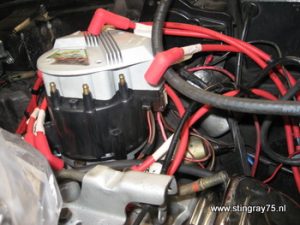
For a hopefully, more or less, I guess… engine startup to run in the camshaft. The timing must be set right. I’ve made black stripes with a permanent marker on the distubutor housing and onto the manifold. By this way we have a good timing mark to start the engine. Note the condesator where I’ve broken off one wire. This means adding soldering to the “Not to forget list”.
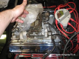
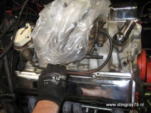
Put a plastic bag over the carburator, you never know what could fall into it.
Now the timing mark has been made the distributor can be taken away. All cables are dismounted.
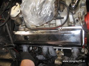
Just an overview picture how it looks now with the distributor cap removed.
Take away the vacuum advance tube from the carb and distributor.
The distributor and the sparkplug cables have been removed.
Disconnect the temperature sendingunit wire from the head.
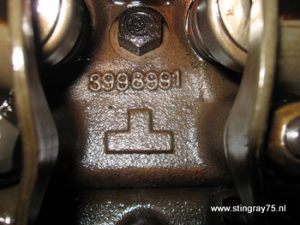
Here is our casting number of the old cast iron heads 3998991. sometimes difficult to read.
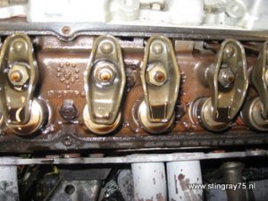
This rocker had less oil inside. I’ve investigated the pushrods, but all were open. (the oil travels through the pushrod to the rocker.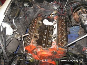
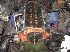
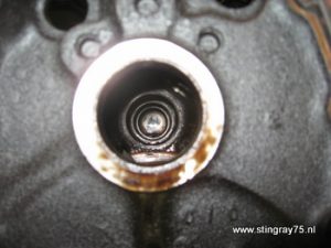
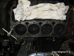
The intake manifod has been removed and all rockers have been taken away. Now is the moment of truth. In what condition are the cylinderwalls and the pistons.
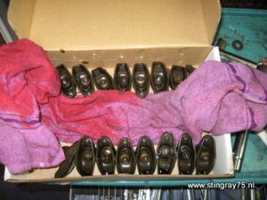
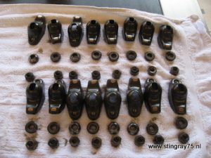
All rockers and pivot balls were stored in order. This is for diagnosis purpose.
The same is done for the pushrods. With permanent marker the cylinders are numbered.
The engine is getting smaller & smaller. Is this the reason they call it a smallblock?
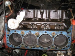
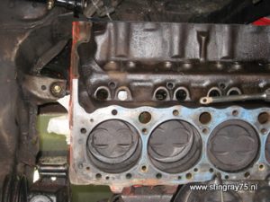
I’m happy that these pistons are not dome pistons, but standard off-the-shelf pistons.
The walls look fine and there is a small ridge of the piston rings. Next time I will measure the bore of the cylinder.
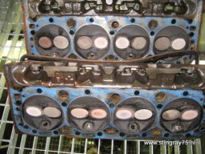
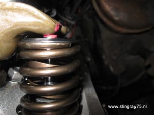
Here are the heads. On 2 forums I’ve asked the question if this looks ok. The valves look white-hot. But this is normal.
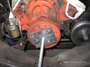
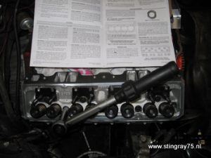
I’ve driven to several companies, but all didn’t have the puller I needed. So I made one with a pulley as template for the hole positions.
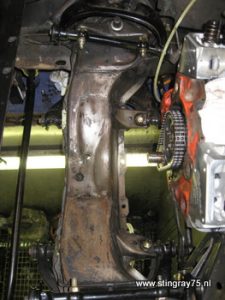
The oil pan has to come loose to remove the iming chain cover. In 2008 the whole suspension was overhauled, except the idler arm an steering box. Now the exhaust is gone the idler arm can be removed. The steering box has been removed as well so this enables me to lower te steering rod and remove the oil pan.
The timing chain and sprockets have been removed. I’ve bought new ones, simply for the fact that we don’t know how long they are in operation.
The lifters have been removed, now we can take out the camshaft
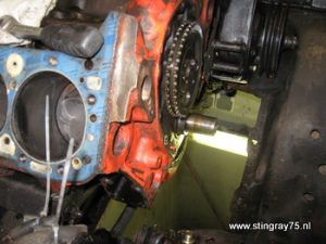
To remove the camshaft put on the sprocket again. This will function as a lever to tilt the end of the camshaft to prevent scoring the bearings.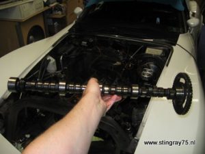
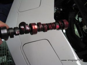
And here is the bumpstick!
Yes there is light at the end of the tunnel!
Now most tings are removed it is time to inspect the components for damage. I’ve cleaned the pushrods with gasoline and a abrasive sponge.
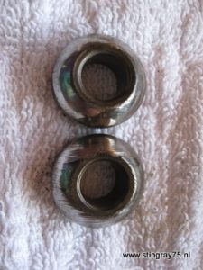
In total 6 pivot balls were quite scored. These must be replaced. Note the score marks on the lower one.
All rockers which are placed thithe the valve tip upwards are worn (scored pivot ball)
All thread holes are tapped to reach accurate torque specs.
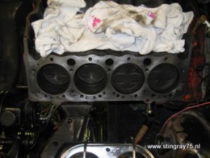
The head surface is cleaned. I’ve used a abrasive 3M sanding mat (contains no grains) with fuel.
A remark of the heartbeatforum is to look for rusted areas because they provide the leaking gasket potential. The areas between the cylinders are narrow and need to be super-super clean.
I’ve kept on cleaning until the white towel was still white.
Now things are clean I’ve put on the gaskets and heads to prevent dirt to enter the combustion chambers.
I’ve put this pagebreak on this position because I allready know the result hehe! Due to an organized car trip (we are the organizating party) I’ve put my effort in finishing the car into the late hours of the evening. It was all worthed :-)))))) Saturday the car was finished and sunday the trip was made of approx 120km (75 miles). The firt part was made with 22 degrees of initial timing 🙁 and after resetting the car was set to 8 degrees. A good baseline to start further testing. The change sure made a big difference. Smiles from ear to ear 🙂 .
I’ll continue the assembly step by step. Show how I’ve done it and what I’ve learned of it.
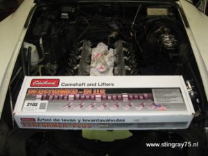
This is the box of the new camshaft. Nothing interesting, but whats interesting is inside.
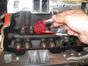
This is camshaft #2102. This kit contains new hydraulic lifters and a red assembly lube.
Here is the assembly lube on the first part of the camshaft which is going to be inserted. As soon as this part is inside the engine, the rest is lubed step-by-step. This way the fingers will be kept clean and things won’t get messy.
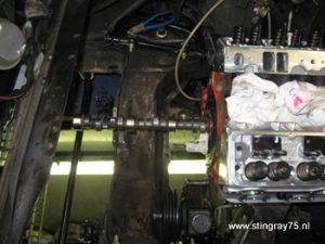
As you can see as well, the chasis has been degreased. Naked metal inderneath. No paint after all those years. This means hammerite to protect the iron until the body off.
Put on the sprocket again to be able to lift the tip of the camshaft. Take your time. Don’t scratch the bearings with the cams!! If it don’t fit immediately, be patient. The tolerances of the camshaft and bearings are tight, but sliding.
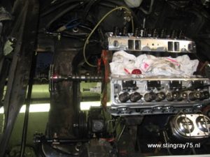
And it is all the way in :-). Now you are probably looking at the bad paint. Indeed a new paintjob is in place.
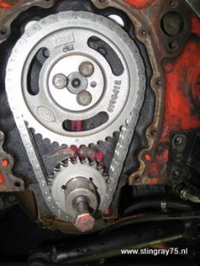
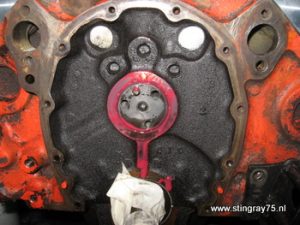
To put on the gears, first put on the bottom gear (I’ve used a hammer and metal tube which fit over the driveshaft. This gear has 3 indexing keys. -4 degrees / 0 degrees / + 4 degrees timing of the camshaft. I’ve chosen for the 0 degree timing because I don’t know what it does yet.
Then put arround the chain around the camshaft gear (which is still not attached). postion the mark downwards and hook the chain onto the driveshaft. Now place the gear onto the camshaft. Place the gear onto the dowel pin and use one screw to fix it.
Use locktite sealant on these bolts! If they come loose it will be very very harmfull for the new heads and engine…..
Check if the chain is running in a straight line. If there is an offset in the two chains, then this is a wrong situation.
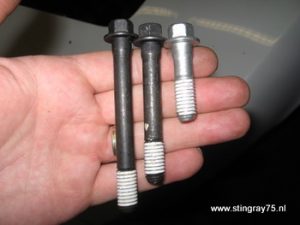
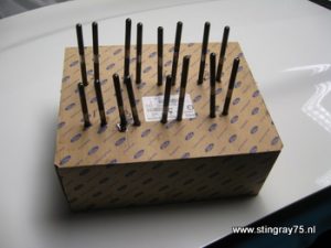
These are the new bolts to hold down all the horses. There is selant on it allready, but I’ve put some silicone blue on them as well. Most bolts are in direct contact with coolant.
The long bolts are used on top of the head. The medium bols are used on top and on the corners. The smallest ones come on the side of the heads.
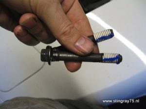
As you can see a small dab of blue silicone.
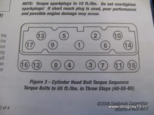
Now it is time to torque the head bolts in 3 steps. 40, 55 and 65 ft/lbs. Use the specs of your head supplier.
I use a calibrated torque wrench. But you need to apply the torque parallell to the bolt.
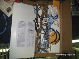
Here is the gasket kit. The head gaskets are allready taken out. This set is perfect for a complete engine build. So this means enough spares for other jobs.
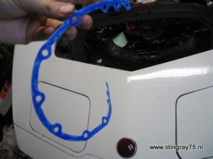
Here is the timing-chain-cover-gasket. What a word. Anyway, it needs a dab of silicone as well.
The timing chain cover is in place. The cover is fitted with a new oil seal. The old one was damaged when I changed the breather on the valve cover. The old one was connected to the air cleaner and provided a continuous vacuum all the time. The other “mushroom” breather gave much resistance to the outcoming carter gasses (read leaking piston rings) that the oil was pushed through the seal and spun around in the engine area. Not a good idea, unless you like cleaning all the time instead of driving.
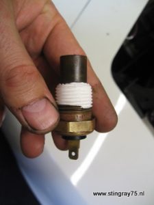
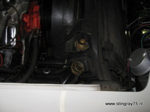
This is the coolant temperature sending unit which is screwed into the cylinderhead on the passenger side. On the other head there is a plug. With all the quick jobs at the end I forgot to put on the teflon tape into the thread. When the radiator was filled with coolant, it started to leak. For a moment I thought the head gasket leaked and there would be a waiting hydrolock. This was luckily not the case.
All the lifters came out without a problem, and the lifters went in quite smoothly. A royal dab of assembly lobe for the first engine revs.
The firing order is 1-8-4-3-6-5-7-2. Rotate the engine in such a way that the cylinder 1 in at TDC ath his compression stroke. Then all valves are closed.
At his moment the pushrods can ve set to zero lash. Turn the rocker nut until you feel drag on the pushrod, when you spin it between your fingers.
Check if the weight of the wrench is not causing the slight drag on the pushrod!
When cylinder 1 is done. Rotate the driveshaft clickwise to bring cylinder 8 to TDC. Follow the same procedure for cylinder 8-4-3-6-5-7-2.
During the zero lash adjustments I saw that sometimes the cylinder was not at TDC. After a few rotations everything was checked for zero lash.
Now it is time to give each rocker nut 1,5 turn. This is possible because we have hydraulic lifters and NOT solid lifters (if you has solids, then skip the 1,5 turns). Do not prelube the lifters, or they will get filled and act as solid lifters.
Edelbrock recommends +0.100″ longer that stock pushrods for a correct rocker geometry. These longer pushrods were ordered at Summit Racing. These rods have hardened balls at the end.
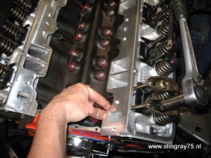
On all friction areas I’ve put the assembly lube, this includes the rocker tip and the valve stem.
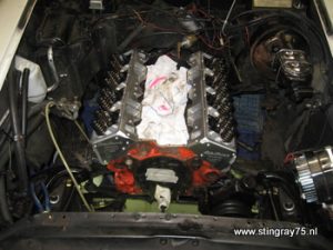
Then the engine looks like this. The cloth is to prevent parts from falling into the engine.