
DIY Stainless steel exhaust with X pipe crossover
It has been on my todo list for a long time now and my stainless steel pipes I’ve bought many years ago, almost started rusting by the waiting in the corner…..
The plan is to produce an exhaust system with an X pipe configuration. It is supposed to scavenge the exhaust gasses from the opening exhaust valve, due to the vacuum created by the last exhaust cycle of the opposite cylinder bank. When a column of gas is in motion and it is stopped, by closing the exhaust valve, there is inertia if this mass which created the ‘vacuum’. The less work the piston has to do, the more horses at the wheels.
More explanation of balance pipes can be found here (Summit Racing): Exhaust ![]() H-Pipes vs. X-Pipes: What You Need to Know
H-Pipes vs. X-Pipes: What You Need to Know
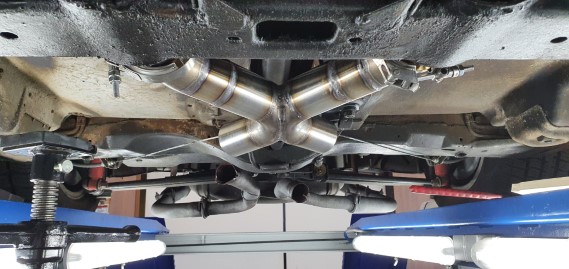
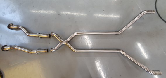
Below is an example of the X- pipe and its position.
The best way to normally test the optimal location for the balance pipe is by painting the exhaust. Where the nodes of a standing wave are , is the best point for the balance pipe. This is where the paint burns off the first.
I has some base paint combination (white + red) available and therefore the nice color pink…..
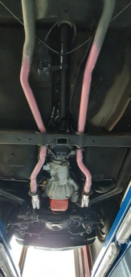
I’ve tried to burn it of twice, but the whole exhaust turned from pink to brown….
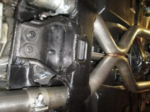
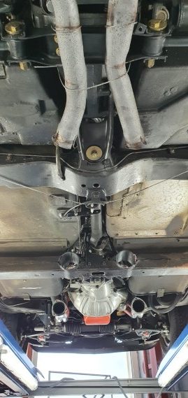
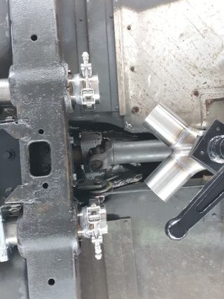
By internet research I’ve found many comments, that there is not an optimal location to place the x pipe, as it would be close to the transmission. The only real available space is at the location of the first picture.
The exhaust was leaking quite a bit. So that problem will be solved. Also the noise level of the glass pack mufflers will be more silenced as 2 mufflers are used instead of one.
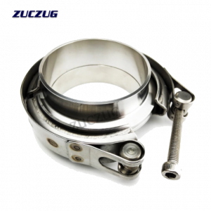
I’m always in trouble in separating the pipes, they are always stuck. This is why I’ve ordered 4 V-band clamps to separate the exhaust segments easier.
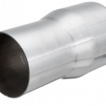
The stainless pipes I had were 2,33 inch in diameter, which is the same as installed. My ceramic headers are 3″ and I’ve found on Ali-express also the flange and reducer.
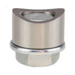
In the past I have installed an Autometer air-fuel monitor oxygen (Lambda) sensor. This required 2 extra bungs as well. Now I can move it from one side to the other for finetuning the carburetor.
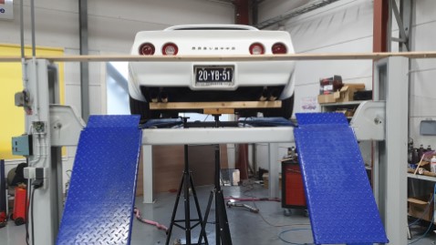
The front section of the exhaust is now removed. Note how a metal cable is suspending the rear section. This has to be changed. It was an emergency fix.
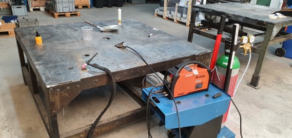
The TIG welding….
Las year we bought a TIG welder at work and I have some experience with MIG welding.
So, after some YouTube training……….., the goal is to do it myself and hope the exhaust is airtight and do this learning curve.
I’ve found some interesting movies of Justin aka “the Fabricator” for TIG welding.
![]() TFS: How to Make X Y H Pipes and Transitions
TFS: How to Make X Y H Pipes and Transitions
![]() TFS: DIY Custom Exhaust from Scratch
TFS: DIY Custom Exhaust from Scratch
After some runs on separate stainless steel plates and understand what my eyes are seeing I’ve made the step to fry the parts together.
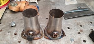
The difficulty was a gap between the muffler flange and the reducer. I’ve managed to fill it with material. I had to regrind the tungsten tip many times, but it’s getting less now. The bung was a lot better. The large bolt absorbs a lot of heat of the welding. The amp setting was too high. I believe 70 amps. This should be in the range of 60. Lesson learned.
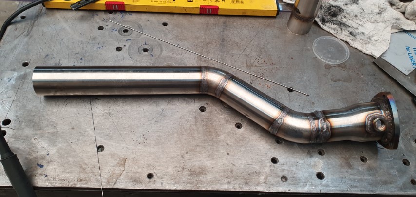
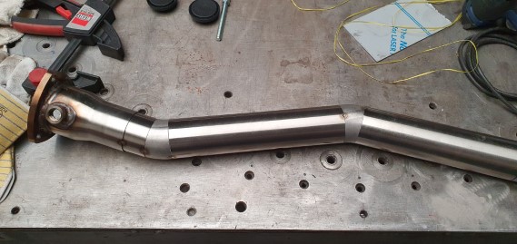
The 2,33″ pipe fits inside the reducer, again with a small gap. I’ve use 90 degree bends to create the turns. It had to go upwards and to the right. Quite some 3D thinking. As a help I had a protractor. When the sections were good, they were spot welded together.
Ooohh this makes me happy.
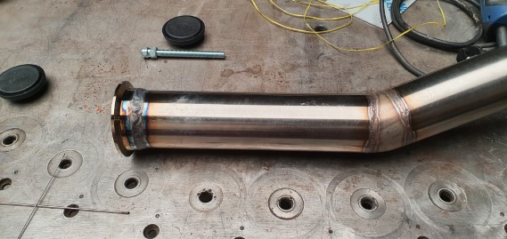
Now it is time to weld this together. The amp setting was now 55.
If the sections are butt joint it is ‘easy’ to do. So the better fitting work, the less trouble for the beginner. The extra metal will be grind off. Not that people will lie under the car to inspect my welds, but is is for my sole discretion.
For the other side I will try to reduce the circumference by making cuts and pull them together.
The X-factor
To make the X pipe, the video TFS: How to Make X Y H Pipes and Transitions was my guide. Very helpful.
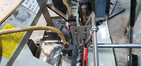
Luckily we have a band saw at work. Just as in the video I’ve added a counter support. When I’ve reviewed the video again, I saw the Fabricator had extra tall plates inside his clamp. This supports the bends a lot better. What I’ve done was on the edge. Lowering the bandsaw with lowest pressure as possible, otherwise the 90 degree bend would be grabbed.
I’ve cut 1/3 of the pipe diameter.
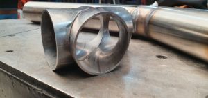
Oooh that looks so nice.
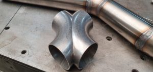
The welding of the in between area was quite difficult. The plasma bow was difficult to focus.
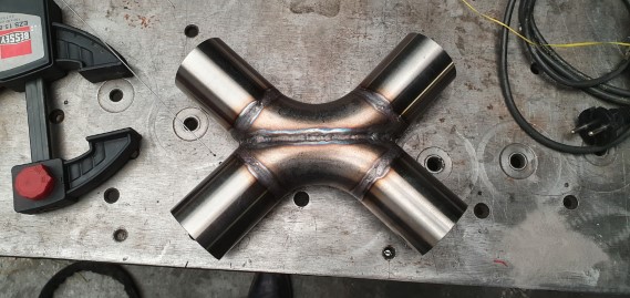
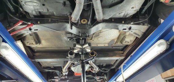
I’ve added some straights to it. Looks like an X to me!
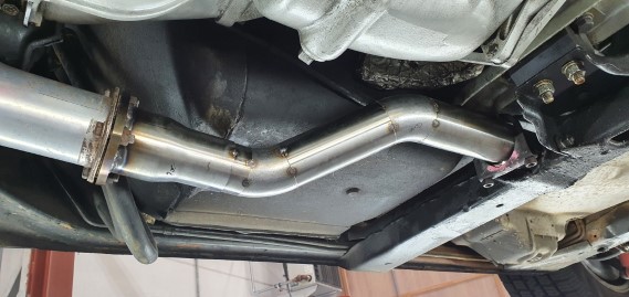
In the meantime I’ve received larger clamps to clamp the exhaust to the bracket. It has to be positioned this way.
On the left side the routing is a bit different due to the gearbox. Also don’t want to fry the reverse switch. The exhaust here is spot welded and need to be fully welded. Then the pipes will be trimmed to length (relative to crossmember) and the V-band clamp will be added. After this I need to add the X factor to it.
Here it is removed from the car.
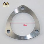
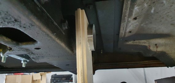
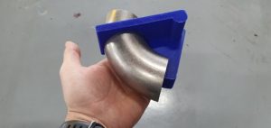
To mark the cutting positions for the left and right side, I’ve used a plank with 76mm hole in it. Easy marking the line now.
After cutting the exhaust was welded, then cut according the line and then the V-band clamp attached. During welding I had to melt off a part of the ring and have also the puddle on the pipe. When more material was needed, it was taken from the ring.
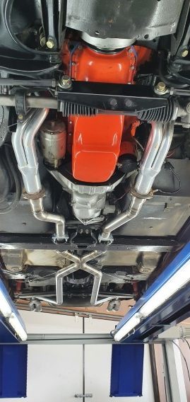
Once everything put back together I had some pictures taken for the X positon. Time to think about it at home.
End of work 15-5-2021
I found it difficult to markt the cutting lines on the 90 degree bends. Last Sunday I had a bright moment. (yes, now and then it suddenly happens 😉 )
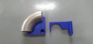
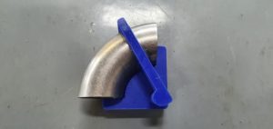
There are marks for 5 and 10 degree sections. Also the inside radius centerline can be marked. Works like a charm. Wish I made this earlier.
If you want to do the same, or modify for different sizes here is the zip file to 2 STL files and the Freecad drawing : 90 degree bend marking tool
Finally the X had been added. The difficulties were, that the slope had to go down. The 2 exhaust with fixed distance have to join the X. And during spot welding the X had to be maintained into position. Underneath the car with welding helmet is annoying, but better than lying underneath your car and trying to do things. Duct-tape was my best friend as a helping hand. Also an angle grinder was a great tool to regrind the tungsten electrode again an again. Saved a lot op trips to the belt grinder 50m away. At some point I’ve added 2 tips to the tungsten. Then I could be more efficient. Welding in a strange position in my case, leads to accidental melting bath dipping.
The positioning and final welding took another 2,5 hours.
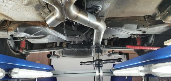
The duct-tape is visible here. Couple more bends and I’ve reached the end of the tunnel. The stand is a great helping hand. The modification of the parking brake has to be changed, as it’s interfering the exhaust.
I’m considering adding a connection point near the bracket of the rear suspension. Note that the last section of the rear exhaust has been removed as well. I need to decide if I change the height of the mufflers and the relative angle. The mufflers are a bit rusted, so a heat resistant paint job is not a luxury. The muffler is regular steel and has the same diameter as the stainless steel tube. I could use a tool to increase the diameter. I’m thinking to weld it together. Maybe a V-band clamp in-between to have the possibility to change it later, but cutting it later and re-welding would be a lighter option. Anyway. One night sleep to think about it. Tomorrow I hope to finish it …
I decided not to use a V-band, but continue with the pipeworks. A wooden beam is used to support the mufflers and keep them level. While the pipe is connected.
Since the muffler is made of normal steel, I can’t weld it to the stainless. It will work with MIG , but it will certainly rust. And taking the muffler off if needed is always a good option. So the picture below shows the reduced diameter of a pipe by cutting out a segment and weld it together again.
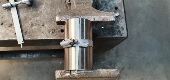
The muffler will slide over this section and the original clamping system will be reused.
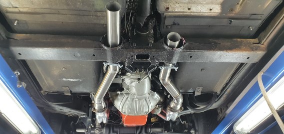
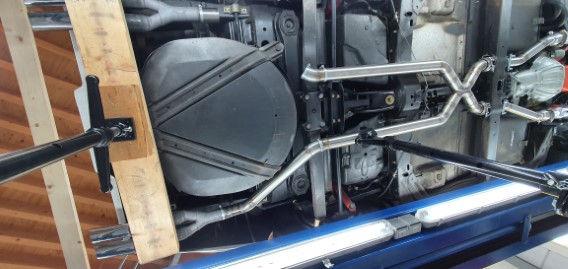
Here is how I wanted the mufflers to appear from the rear. I’ve shorteded the brackets to the car to raise the muffler heigth.
Now everything has been spotwelded, the rear end was welded completely. Now it is time for final assembly.
While the headers were gone, it was a good moment to paint the chassis sections with some fresh Hammerite. Better this than nothing.
And now… The moment we have been waiting for……
After taking the vette for a drive, it was a very good sound. Suddenly all the noise was coming from the rear of the car instead of all over the place. Completely different.
Just it time to drive my son towards his gala event.