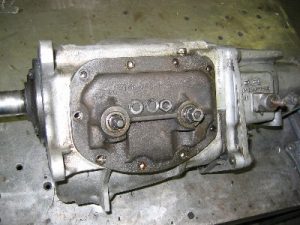
Yep, Here are some pictures how I have dismantled the manual transmission.
Remove the transmission from your car as per your shop manual’s instructions. Thoroughly clean the exterior. After the transmission is clean you can look for the transmission code and VIN numbers stamped into the case. If the last 6 digits of your VIN number match the last 6 digits stamped on the transmission case, you have the original transmission for your Corvette. This was in our case. We have a genuine manual speed.
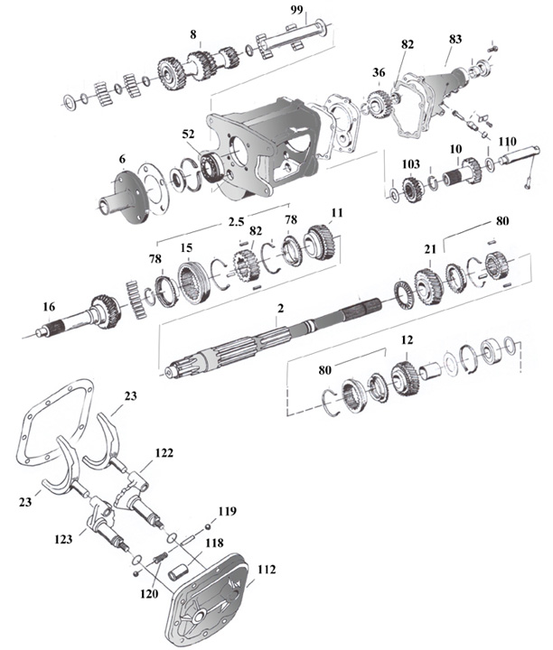
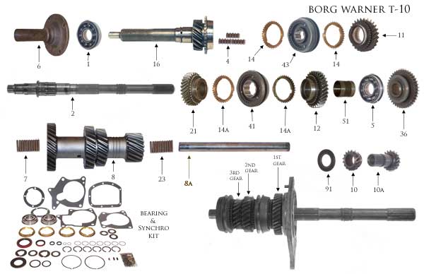
At the end of this article are diagram pictures of the transmission. I’ve used this for the overview.
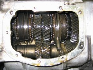
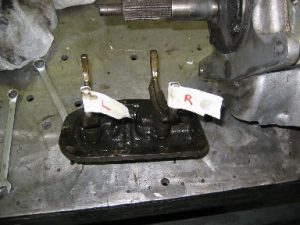
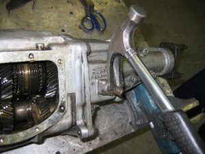
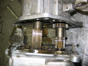
Drain the transmission then remove the 9 bolts that hold the side cover in place. Carefully remove the cover and shifting forks.

The shifter fork of the 1rst and 2nd gear is still in place.
Mark the shifting forks with their corresponding clutch assemblies. Also make sure you mark which end of the fork was at the top of the clutch assembly. These forks wear with the clutch assembly as they move back and forth so you want them to stay with their respective clutch assemblies.
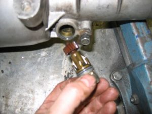
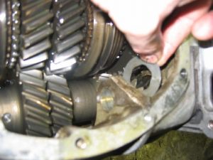
Remove the retaining bolt and clip and pull the speedometer gear out of the tailshaft of the transmission.
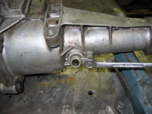
With the speedometer gear removed check for any worn, broken, cracked, chipped or flattened teeth. If you find any, replace the gear.
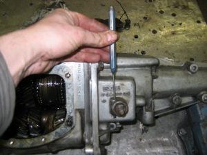
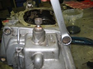
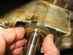
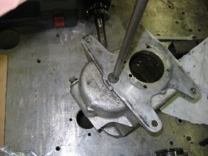
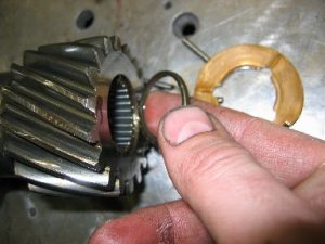
Drive out the lock pin from the reverse shifter boss. (Look carefully at the end of the pin. You will see that one end is thicker than the other and can only be removed in one direction. Drive the pin out from the bottom of the boss to the top.) THE DIRECTION IN THE PICTURE IS WRONG. It must be done in the opposite direction.
Pull the shifter shaft out partially to disengage the fork from the reverse gear. Screw a nut on the thread to protect it. Use something to pull. I’ve used a hammer to do the Job. Whatever you do, don’t damage the threads.
Remove the 5 bolts that attach the tailshaft to the transmission main case.
Use a soft blow hammer to tap the tailshaft rearward until the reverse idler shaft is clear of the reverse idler gears.
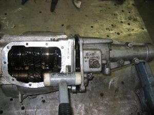
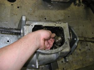
Now rotate the tailshaft to the left. Turn the reverse shifter shaft to free the fork from the gear and remove the tailshaft. Clean off any of the old gasket.
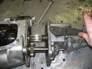
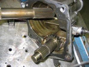
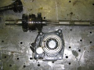
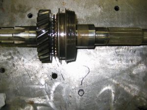
And here is the result. When the tailshaft is removed, the inner reverse gear will come loose in the remaining housing.
The reverse gear is below in the picture. We need an extra gear to be able to reverse the direction of course. This is the one…
Remove the thrust washer from the left side of the gear. This will be replaced with the rebuild kit.
After taking of the reverse gear of the extension housing, the thrust washer is visible. Take it off and look at the notch. This should fit in the recess in the extension housing. This one will be replaced as well.
Now the extension housing is taken off. (note: the reverse gear and thrust washer are still there)
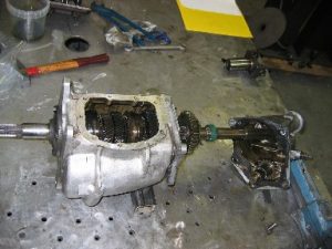
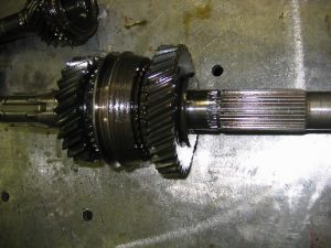
Now it’s time for an overall picture.
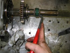
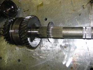
Remove the speedometer gear outer snap ring and then tap or slide the gear off the shaft. The second snap ring can now be removed. Here you can see the snap rings and gear are removed from their position on the shaft. Measure the thickness of the rings. In the rebuild kit are several rings with different thicknesses.
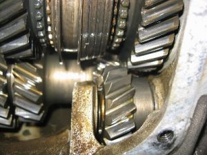
Note: On the left of the speedometer gear is the reverse gear.
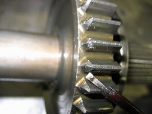
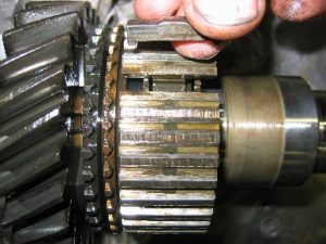
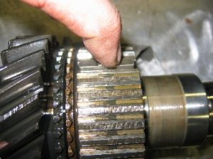
This is what happens, when the gears are rotating and the reverse gear is engaged. Rounding off teeth is the result. I’ve decided to reuse the gear. Since it is there for 32 years and it takes for ever to grind it off completely.
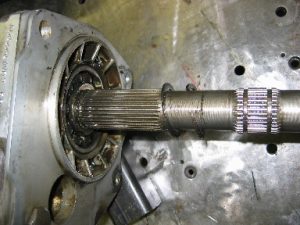
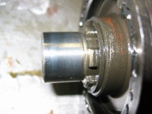
Remove the 4 input shaft collar retaining bolts and gasket from the front of the transmission. You may need a soft blow hammer to tap it loose.
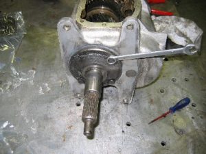
And again the work is progressing.
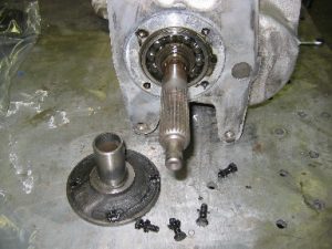
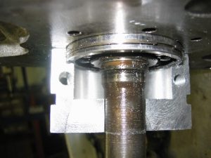
Now remove the front bearing snap rings and washer.
Here is a detail of the snap ring and washer.
I’ve also taken off the snapring on the side of the extrension housing.
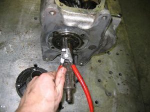
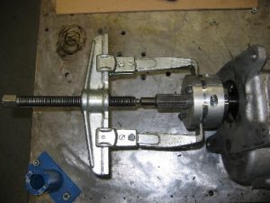
To remove the front bearing I’ve made a dedicated alluminium puller. The removal of this bearing took me two days. This was realy a pain in the @ss. But finally with penatrating oil and Dutch mucle power the bearing lost its battle.
The snapring in not removed in this case.
Here is how the puller works. There are several pullers which can be used.
Next remove the rear retainer lock bolts.
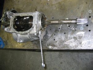
Tap the rear retiner loose with a soft hammer.

Now is a good time to take out the reverse gear out of the main case.
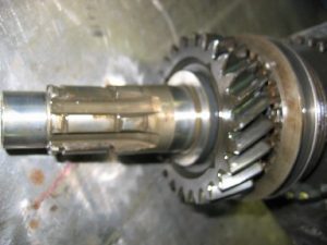
Carefully slide the input shaft out of the case. The inside of the shaft is full of roller bearings so be careful during removal or you will be chasing these bearings all over the shop floor. The roller bearings will be replaced.
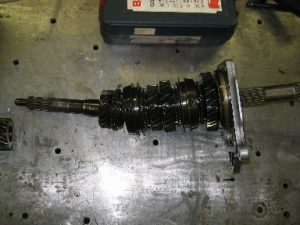
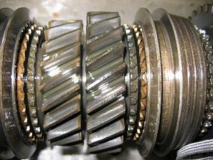
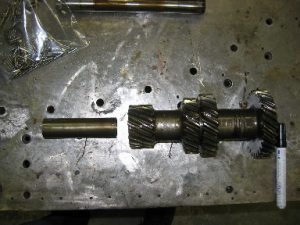
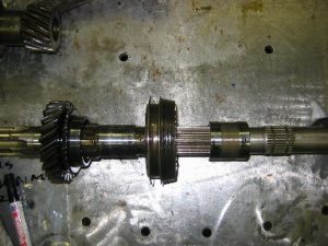
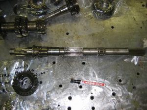
Here is detail picture #1 of the complete assembly of the main shaft. After reassembling it should look like this.
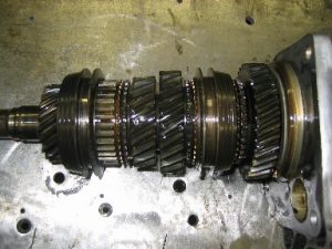
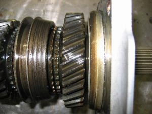
Detail picture #2. On the left the 4th grear. The next one is the 3rd gear. The 4th gear is actually fixing the inputshaft to the output shaft. The Ratio is then 1:1.
Detail picture #3. On the left 3rd gear, and then the 2nd gear.
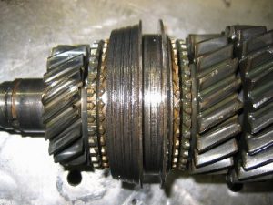
Detail picture #4. The hub for the 2nd and the 1rst gear. (seen from left to right).
Detail picture #5. The first gear.
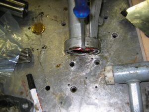
Use a dummy shaft to drive out the shaft of the countergear. I’ve positioned the housing and the shaft on top of a hole in my table. It’s convenient sometimes. Most of the times it is annoying. The countergear shaft will be replaced. Take care of the woodruff key which will fall out. This key will hold the counter gearshaft in its position (axial and rotational)
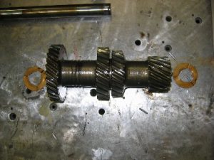
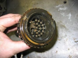
And here is the counter gear. It is made out of one piece. Note the type of thrust washers in the sides. Thes will be replaced as well. As soon as it is loose the needles will find it’s way to freedom after a long time in prison.
A detail of a ring (there are more of them, se assembly section) this will hold the needles in place and prevent it from moving in axial direction.
In the middle of the 4 needle bearing sets is a metal distance tube.
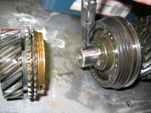
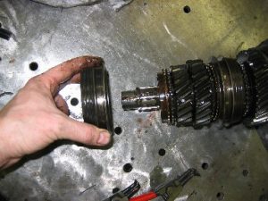
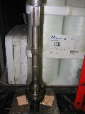
This is the input shaft also called the prise shaft. This gear will power the couter gear shaft and it is functioning as the 4th gear. Remember the 1:1 ratio.
There are 16 Needle rollers. They will be replaced as well.
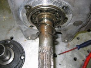
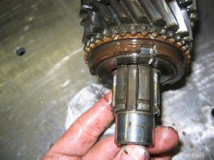
Carefully check this area of the mainshaft. It rides in the input shaft. If it has pits, scores, gouges, knicks or grooves, the mainshaft will have to be replaced. Mine was ok. Well you can’t hurt the gearbox with only 165HP duh.
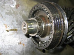
Here is a detail of proof.
Remove the snap ring from the end of the mainshaft. (Tip: measure the thickness)
Remove the slide the washer
Then the synchronizer and clutch assembly, synchronizer ring …..
and 3rd gear from the mainshaft.
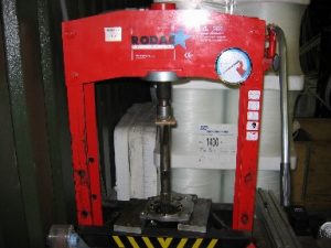
Support the rear bearing retainer (make sure it is evenly supported, so it can’t bend) in a press and press the mainshaft out of the bearing. The remaing gears to be removed are inside the press.
The result.
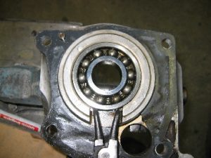
Remove the rear bearing to rear retainer snap ring and remove the bearing from the plate. A simple but clever system.
This is the assembly which has to be removed.
Fist take off the thrust washer.
Here is the (indexing) key of the hub assembly. These have to be replaced with the new ones. Mines weren’t bad but new ones came with the rebuild kit.
Note that the first gear is taken off.
This is how it looks like when it is installed,
To take off the 2nd gear it was inpossible to do it by hand, so again the press was very usefull.
Here the 2nd gear is pressed off again in a hydrailic press. Cardboard is used to preventdamages.
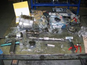
Everything is bagged and tagged. Make as much as pictures as possible and use a separate bag for each component. At the end you have a big pile of parts.
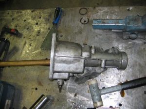
Now everything is dismanteled. Time to look at the housing.
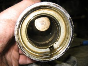
This was one of the main reason to rebuild the gearbox. The endseal went incontinent.
Use a prying tool to remove the seal.
Use a brass hammering tool to hammer out the bushing. This way the housing is not damaged.
And here is the carcas after the crime.
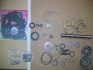
The rebuildkit contains everything you need:
- Gaskets
- All types of bearings, needles
- Synchronising rings an keys
- Washers
- Oil seal ring
- Countergear shaft
- Snaprings
![]()